5. Object Reference
FlatCAM Objects are the documents FlatCAM operates with. For an introduction see Objects and Tasks.
5.1. Gerber Object
5.1.1. Format
The Gerber Format specifies polygons. Shapes that have an area. Most commonly copper regions in a specific layer of a PCB. It is also used for solder masks, solder paste and artwork.
A short Gerber file looks like this:
G04 This line is a comment an is ignored.*
G04 Coordinate format specification:*
%FSLAX25Y25*%
G04 Set units to inches:*
%MOIN%
G04 Define an aperture:*
%ADD10C,0.100*%
G04 Change polarity to DARK:*
%LPD*%
G04 Select the the previously defined aperture:*
D10*
G04 Set interpolation mode to linear:*
G01*
G04 Move to (0, 0) without drawing:*
X0Y0D02*
G04 Draw to (5, 5) using aperture 10:*
X500000Y500000D01*
G04 Enf of file:*
M02*
5.1.2. Support
The Gerber File Format is fully supported with the following exceptions as of version 8.2:
- Holes in standard apertures are not supported.
- Interpolation is always done with a circular aperture even if a non-circular aperture is chosen. An equivalent size is calculated from the dimensions of the aperture and used as the diameter of a circular aperture. This is unlikely to ever affect a gerber for a PCB. This limitation does not affect flashing.
- Step and Repeat (SR) is not supported.
5.1.3. Creation
Gerber Objects are created by the following methods:
- Opening a Gerber file using the File→Open Gerber menu option.
- Opening a Gerber file using the File→Open Recent menu option
- Opening a Gerber file using the open_gerber command in the Shell Command Line Interface.
- Importing an SVG file using the import_svg command in the Shell Command Line Interface.
5.1.4. Operations
5.1.4.1. Isolation Routing
Parameters:
- Tool dia \(d\): The diameter of the cutting tool.
- Width (# passes) \(n\): Width if the isolation gap in number of tool diameters.
- Pass overlap \(\theta\): Fraction of the tool diameter to overlap each pass.
Generates a Geometry Object describing the tool path to cut outside the perimeter of the polygons described in the Gerber file. The first tool path is at a distance \(D = d/2\) outside the polygon. If \(n>1\) then there will be \(n-1\) additional tool paths at a distance \(D = d(1-\theta)\) from the previous pass.
Isolation routing is available in the GUI and via the isolate command in the Shell Command Line Interface.
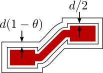
Isolation Routing example with \(n=2\).
5.1.4.2. Board Cutout
Parameter:
- Tool dia \(d\): The diameter of the cutting tool.
- Margin \(m\):
- Gap size \(g\):
- Gaps: Takes the following possible values:
- 2 (T/B): Two gaps, at top and bottom sides.
- 2 (L/R): Two gaps, at left and right sides.
- 4: Gaps on all 4 sides.
Generates a Geometry Object with a rectangular tool path around the geometry in the Gerber Object. The tool path includes gaps that will prevent the board being cut from completely detaching from the parent board while cutting.
The Board Cutout operation is available in the object’s GUI or via the cutout command in the Shell Command Line Interface.
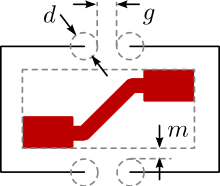
Board Cutout operation dimensions.
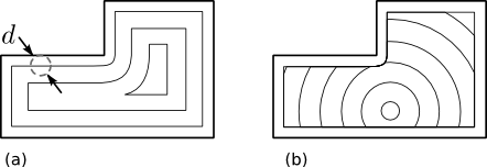
5.1.4.3. Non-copper Regions
Parameters:
- Boundary Margin \(m\): Distance from the smallest possible bounding box.
- Rounded Corners:
Generates a Geometry Object with polygons of the empty areas in the Gerber Object, this is, where there is no copper.
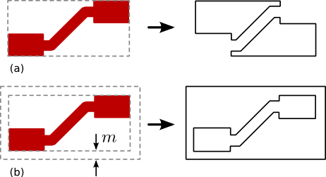
Non-copper region generation. (a) Example with zero margin. (b) Example with non-zero margin.
The Non-copper Regions operation is available through the object’s GUI.
5.1.4.4. Bounding Box
Parameters:
- Boundary Margin \(m\): Distance from the smallest possible bounding box.
- Rounded Corners : If set, then the corners will be rounded with a radius \(m\).
Generates a Geometry Object with a rectangular path around the geometry in the Gerber Object at a distance \(m\) from the smallest possible bounding box. If using rounded corners, their curvature radius will also be \(m\).
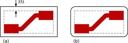
Bounding box generation for Gerber Objects. (a) Without rounded corners. (b) With rounded corners.
The Bounding Box operation is available through the object’s GUI.
5.1.4.5. Scale
Parameters:
- Factor \(k\): Factor by which to multiply the geometric
features of the object. Example:
2.54.
Modifies the Gerber Object by changing its dimensions. The geometry in the Gerber Object is multiplied by the given factor. E.g. if factor is \(k=2\), the geometry will be doubled in size. Consequently, any coordinate point that was originally at a distance \(d\) from the origin, will be at \(2d\).
The scale operation is available in the GUI and via the scale command in the Shell Command Line Interface.
5.1.4.6. Offset
Parameters:
- Vector \(v\): Coordinate pair by which to translate the geometric
features of the object. Example:
(1.0, -2.0).
Modifies the Gerber Object by translating its coordinates. All coordinates in the Gerber Objects are added to the given vector. I.e. if \(v=(x_v,y_v)\) then all points \((x,y)\) will be translated to \((x+x_v, y+y_v)\).
The offset operation is available in the GUI and via the offset command in the Shell Command Line Interface.
5.1.4.7. Follow
Note
The Follow operation is not fully functional yet. For an overview on how it currently operates, visit the blog post Tracing the Silkscreen with FlatCAM.
5.1.4.8. Mirror
Parameters:
- Mirror Axis: Axis around which to mirror the object’s geometry.
I.e.
XorY. - Axis Location: The location of the mirror axis can be specified
in one of two ways:
- A Point through which the the axis passes. E.g.
(1.0, -2.0), then if the axis isXthen it is a horizontal line passing through \(y=-2.0\). If it’s theYaxis, it is a vertical line passing through \(x=1.0\). This option is only available in the Double-Sided PCB Tool. - A Rectangle which is divided by the axis in half. In this case, a Geometry Object containing a single rectangle is specified.
- A Point through which the the axis passes. E.g.
Mirrors the geometry in the object around a specified axis.
This operation is available via the Double-Sided PCB Tool (see 2-side PCB) and the millholes command in the Shell Command Line Interface.
5.2. Excellon Object
5.2.1. Format
The Excellon File Format specifies how a circuit board should be drilled.
Excellon files are text files with tools and holes directives. An short Excellon file looks like this:
; This line is a comment and is ignored
; The next line starts the "header":
M48
; Units and number format:
INCH,LZ
; One tool is defined with diameter 0.04 inches,
; drill rate of 300 inches/minute and 55000 RPM.
T1C.04F300S55
; End of header, M95 or %, and beginning of body:
M95

; Use tool 1 defined in the header
T1
; Drill at points (123.45, 234.5) and (12.345, 234.5):
X12345Y23450
X012345Y234500
; End of program;
M30
Unfortunately, the format is not very well specified and there is room for ambiguity. Several CAD programs will implement the format incorrectly making it impossible to interpret as intended. FlatCAM attempts to follow the original specification as strictly as possible and defaults to the following values when not clearly specified in the file:
5.2.2. Support
- FlatCAM only supports drilling. Routing directives in Excellon are not supported.
- The default units are INCHES.
- Number format is 000.000 for millimeters and 00.0000 for inches.
- Zero format is Leading. If less than 6 digits are provided, they are added by FlatCAM to the right of the number. Leading zeros are assume present.
- Tool definitions in the body (After
M95) are not supported.
5.2.3. Overriding defaults
To override the zeros format default, set the system parameter excellon_zeros in the Shell Command Line Interface:
set_sys excellon_zeros T
5.2.4. Creating Excellon Objects
Excellon Objects are created by opening an Excellon file:
- The File→Open Excellon menu option
- The File→Open Recent menu option
- The open_excellon command in the Shell Command Line Interface.
5.2.5. Operations
5.2.5.1. Create CNC Job
Parameters:
- Cut Z: Drill depth below the copper surface. E.g.
-0.1. - Travel Z: Distance above the copper while moving in the X-Y plane.
- Feedrate: Tool speed while drilling (Z axis movement) in units per minute.
E.g.
50. - Tool change: If set, will include tool changing sequence in the resulting G-Code.
- Tool change Z: Distance from the copper surface to lift the tool
for it to be changed. E.g.
1.2. - Tools: List of tools that will be included in the CNC Job.
Creates a CNC Job Object for drilling.
A CNC Job for the Excellon object can be created via the object’s GUI or the drillcncjob command in the Shell Command Line Interface.
5.2.5.2. Mill Holes
Parameters:
- Tool dia: Diameter of the milling tool.
- Tools: List of tools that will be included in this operation.
Creates a Geometry Object with tool paths for milling holes specified in the Excellon object.
5.2.5.3. Scale
- Factor \(k\): Factor by which to multiply the geometric
features of the object. Example:
2.54.
Modifies the Excellon Object by changing its dimensions. The coordinates of drill holes in the Excellon Object are multiplied by the given factor. E.g. if factor is \(k=2\), a point originally at \((x, y)\) will be tanslated to \((2x, 2y)\). The drill diameters are not affected.
The scale operation is available in the GUI and via the scale command in the Shell Command Line Interface.
5.2.5.4. Offset
- Vector \(v\): Coordinate pair by which to translate the geometric
features of the object. Example:
(1.0, -2.0).
Modifies the Excellon Object by translating its coordinates. All coordinates in the Excellon Objects are added to the given vector. I.e. if \(v=(x_v,y_v)\) then all points \((x,y)\) will be translated to \((x+x_v, y+y_v)\).
The offset operation is available in the GUI and via the offset command in the Shell Command Line Interface.
5.2.5.5. Mirror
Parameters:
- Mirror Axis: Axis around which to mirror the object’s geometry.
I.e.
XorY. - Axis Location: The location of the mirror axis can be specified
in one of two ways:
- A Point through which the the axis passes. E.g.
(1.0, -2.0), then if the axis isXthen it is a horizontal line passing through \(y=-2.0\). If it’s theYaxis, it is a vertical line passing through \(x=1.0\). This option is only available in the Double-Sided PCB Tool. - A Rectangle which is divided by the axis in half. In this case, a Geometry Object containing a single rectangle is specified.
- A Point through which the the axis passes. E.g.
Mirrors the geometry in the object around a specified axis.
This operation is available via the Double-Sided PCB Tool (see 2-side PCB) and the millholes in the Shell Command Line Interface.
5.3. Geometry Object
Geometry Objects are the core geometry representation in FlatCAM. They can be manipulated in multiple ways including the conversion to and from other formats and kinds of objects.
5.3.1. Creating Geometry Objects
Geometry Objects can be created in different ways:
5.3.1.1. From Scratch
A blank Geometry Object can be created with:
- The menu Exit→New Geometry.
- The New Geometry toolbar button.
- The new_geometry command in the Shell Command Line Interface.
5.3.1.2. From Other Objects
Geometry Objects can be generated from a:
- Gerber Object
- Isolation Routing
- Board Cutout
- Non-copper regions
- Bounding box
- Follow
- Excellon Object:
- Mill Holes
- Geometry Object:
- Paint Area
5.3.1.3. From SVG
FlatCAM can import Scalable Vector Graphics (SVG) files as Geometry Objects. You can import an SVG file using:
- The File→Import SVG menu item.
- The import_svg command in the Shell Command Line Interface.
This feature allows FlatCAM to generate G-Code for complex artwork that might be too complex to create in your PCB editing software.
SVG files, like most graphic formats use a coordinate system with the origin at the top-left corner. FlatCAM will modify the origin to be at the bottom-left corner based on the dimensions of the image.
SVG files can be created using free software like Inkscape or commercial software like Adobe Illustrator.
FlatCAM can also export Geometry objects as SVG files. See geo2svg.
5.3.2. Operations
5.3.2.1. Editing
A Geometry Object can be manually edited in the Geometry Editor.
5.3.2.2. Create CNC Job
Parameters:
- Cut Z: Cutting depth (negative) below the copper surface.
- Travel Z: Distance above the copper surface while moving without cutting.
- Feed Rate: Cutting speed in the X-Y plane in units per minute.
- Tool dia: Diameter of the cutting tool.
- Spindle Speed: (Optional) Speed of the spindle in revolutions per minute (RPM).
- Multi-Depth and Depth/pass: Use multiple passes to limit the cut depth in each pass to the specified value.
Creates a CNC Job Object tracing the paths in the Geometry Object.
This operation is available through the object’s GUI and the aligndrill command in the Shell Command Line Interface.
5.3.2.3. Paint Area
Parameters:
- Tool dia: Diameter of the cutting tool.
- Overlap: Fraction of the tool to overlap each pass.
- Margin: Distance by which to avoid the edges of the polygon to be painted.
- Method: The following methods are available:
- Standard: The target polygon is shrunk by the tool diameter until no area remains.
- Seed-based: A point inside the target polygon is calculated and it is enlarged until no segment of the resulting circle intersects the target polygon.
- Polygon: Polygon defining the region to be painted. The polygon is automatically identified by specifying a point inside the polygon.
Generates a new Geometry Object with tool paths covering the whole surface of the specified polygon.
Geometry generated by the Paint Area operation applied to the same polygon using the (a) Standard Method and the (b) Seed-based method.
This operation is available through the object’s GUI and the paint_poly command in the Shell Command Line Interface.
5.3.2.4. Scale
- Factor \(k\): Factor by which to multiply the geometric
features of the object. Example:
2.54.
Modifies the Geometry Object by changing its dimensions. The geometry in the Object is multiplied by the given factor. E.g. if factor is \(k=2\), the geometry will be doubled in size. Consequently, any coordinate point that was originally at a distance \(d\) from the origin, will be at \(2d\).
The scale operation is available in the GUI and via the scale command in the Shell Command Line Interface.
5.3.2.5. Offset
- Vector \(v\): Coordinate pair by which to translate the geometric
features of the object. Example:
(1.0, -2.0).
Modifies the Geometry Object by translating its coordinates. All coordinates in the Geometry Objects are added to the given vector. I.e. if \(v=(x_v,y_v)\) then all points \((x,y)\) will be translated to \((x+x_v, y+y_v)\).
The offset operation is available in the GUI and via the offset command
5.4. CNC Job Object
CNC Job Objects are a simple representation of G-Code in FlatCAM. There are few operation available for this type of object. Most options are set at the time the object is generated.
5.4.1. G-Code Format Support
The G-Code understood and generated by FlatCAM follows the NIST G-Code Guidelines but supports only a small subset of commands required for planar operations. When importing G-Code all codes that are not relevant to the 2D view in FlatCAM are ignored.
5.4.2. Creating CNC Job Objects
CNC Job Objects can be created in different ways:
- Opening a G-Code file via:
- The File→Open G-Code menu option
- The File→Open Recent menu option
- The open_gcode command in the Shell Command Line Interface.
- From a Geometry Object
- Create CNC Job
- From an Excellon Object
- Create CNC Job
5.4.3. Overriding Defaults
5.4.3.1. Coordinate Format
The coordinate format in output G-Code defaults to:
X%.4fY%.4f
For example: X12.3000Y0.4090.
This can be modified, for example, to change precision, add space between X and Y values, or change to lowercase by using the system parameter cncjob_coordinate_format in the Shell Command Line Interface:
set_sys cncjob_coordinate_format "x%.3f y%.3f"
5.4.3.2. Z-axis speed
The speed on the Z-axis defaults to maximum (G00) in the positive direction (up) and to the same speed specified for XY when moving in the negative direction (down).
The default speed in the negative/down direction can be modified changing the system parameter zdownrate in the Shell Command Line Interface:
set_sys zdownrate 3
The value is in units/minute, where units are whatever units are active in the current project.
5.4.4. Operations
5.4.4.1. Export G-Code
Parameters:
- Prepend to G-Code: Any text provided will be added at the beginning of the G-Code file.
- Append to G-Code: Any text provided will be added to the en of the G-Code file.
- File Name: Name of the file to write.
Saves the G-Code of the Object in the specified file.
This operation is available in the object’s GUI and through the set_sys command in the Shell Command Line Interface.